Understanding Can Velocity in Baghouse Dust Collectors
Definition of Can Velocity in Bag Filters
Can velocity in bag filters refers to the upward speed of the airstream as it travels through the lower plenum and filtration chamber of a baghouse dust collector. It measures the vertical upward movement of dirty process gas within the housing before the air passes through the filter media.
Calculated in feet per minute (FPM) or meters per second (m/s), can velocity determines whether dislodged dust particles can successfully settle into the hopper or remain suspended in the airstream. As a custom bag filter manufacturer, optimizing this parameter is central to engineering high-efficiency systems.
Can Velocity vs. Interstitial Velocity
While both metrics evaluate airflow speed within the collector housing, they measure distinct operational zones:
- Can Velocity: Evaluates total volumetric air flow divided by the open cross-sectional area of the filter housing directly beneath the filter bags.
- Interstitial Velocity: Measures the accelerated air speed in the tight spaces directly between the filter bags, accounting for the physical volume the bags occupy.
| Parameter | Measurement Zone | Operational Impact |
|---|---|---|
| Can Velocity | Lower plenum / area below bags | Determines dust drop-out efficiency into the hopper |
| Interstitial Velocity | Gaps between individual filter bags | Controls localized bag abrasion and particle re-entrainment |
Relationship Between Air-to-Cloth Ratio and Can Velocity
The air-to-cloth ratio and can velocity are primary design variables that directly govern dust collector performance:
- Air-to-Cloth Ratio: Represents the volume of gas passing through a unit area of filter fabric (CFM/sq ft or m³/m²/min).
- Can Velocity: Controls the vertical lift force acting against falling dust during pulse jet cleaning cycles.
Maintaining a conservative air-to-cloth ratio is insufficient if the can velocity is unmanaged. If upward airflow velocity exceeds the terminal settling velocity of the isolated dust particles, dislodged dust cake cannot drop out of suspension. Instead, dust immediately re-attaches to adjacent filter bags, driving up differential pressure and shortening filter bag service life.
Why Can Velocity Matters in Dust Collector Design
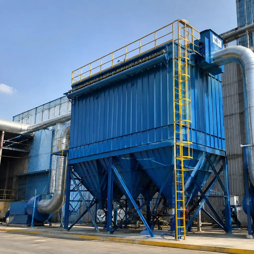
Can velocity directly dictates how smoothly air and dust move inside a filtration chamber. Getting the upward airstream velocity right ensures that separated dust drops cleanly into the hopper rather than clinging to the filter media.
Preventing Dust Re-entrainment
When the can velocity of bag filters is too high, pulse jet cleaning loses efficiency. Dust blasted off the bags gets caught in the upward airflow and immediately snaps back onto adjacent bags—a problem known as particle re-entrainment.
- Targeted Airspeed: Keeping upward air speed lower than the terminal settling velocity of the dust particle allows gravity to pull heavy dust cakes down.
- Hopper Collection: Lower velocities guarantee that knocked-off dust drops smoothly into the hopper instead of remaining suspended in the airstream.
Controlling Differential Pressure Drop
High upward airspeed locks dust against the filter surface, preventing natural cake discharge. As a result, the baghouse dust collector works harder to push air through, causing a steep spike in differential pressure and increasing fan energy consumption. Installing optimized dust collector bag filters helps maintain steady pressure across the entire system.
Extending Filter Bag Service Life
Excessive velocity accelerates wear on filter media through continuous particle bombardment and constant high-pressure pulsing. Managing this air speed protects your equipment investment and ensures long-term operational stability.
| Impact Area | Uncontrolled High Can Velocity | Optimized Can Velocity |
|---|---|---|
| Filter Bag Wear | Severe particle abrasion and premature bag failure | Minimal wear with extended bag service life |
| System Pressure | Unstable, high differential pressure drop | Baseline, predictable differential pressure |
| Cleaning Cycles | Continuous, aggressive pulse jet cleaning | Periodic, highly effective pulse cleaning |
| Energy Usage | High fan power demand to overcome resistance | Low, efficient system energy consumption |
How to Calculate Can Velocity for Bag Filters
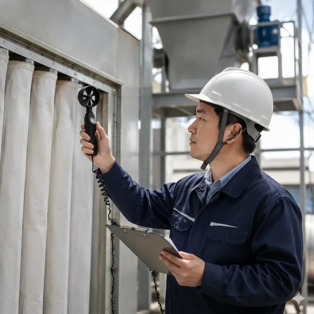
Calculating the can velocity of bag filters is essential to prevent dust re-entrainment and keep your baghouse dust collector running efficiently. We use a straightforward mathematical approach to measure how fast the air travels upward through the open space between the filter media inside the filtration chamber.
Formula for Calculating Can Velocity
To find the can velocity, divide your total volumetric air flow rate by the net free cross-sectional area of the housing:
- Can Velocity (FPM) = Volumetric Airflow Rate (CFM) / Net Free Area (sq. ft.)
Where: Net Free Area = Total Housing Cross-Sectional Area – Total Area Occupied by Filter Bags Bag Area Footprint = Number of Bags * (3.1416 * (Bag Diameter in feet / 2)^2)
Always keep unit measurements consistent. If your airflow rate is in CFM, measure your housing dimensions in feet to get feet per minute (FPM).
Key Variables: Airflow, Housing Area, and Bag Dimensions
Calculating this metric accurately depends on three essential system variables:
- Volumetric Airflow Rate: The total volume of contaminated gas entering the dust collector, typically measured in CFM or m³/h.
- Housing Cross-Sectional Area: The internal width multiplied by the internal length of the filter housing shell.
- Bag Dimensions and Quantity: The outer diameter, length, and total count of bags mounted in the tube sheet.
Balancing these inputs prevents excessive airstream velocity and avoids operating issues. When evaluating system performance, comparing filters for resistance and efficiency helps ensure your calculated velocity supports optimal pressure drop and long-term bag life.
Using a Can Velocity Calculator
While manual calculations are quick, using an automated baghouse calculator speeds up the design phase and eliminates human error.
Using a dedicated calculator helps you:
- Evaluate Layout Options: Test different bag diameters, quantities, or cage arrangements in real time.
- Avoid Velocity Bottlenecks: Instantly spot tight bag spacing that restricts upward air movement.
- Optimize Filtration Balance: Pair your target air-to-cloth ratio with safe upward velocities to protect the dust cake during pulse jet cleaning.
Recommended Can Velocity Guidelines
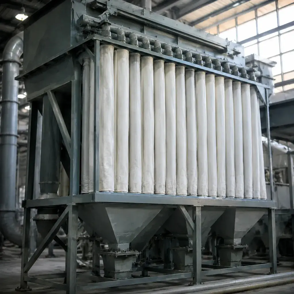
Setting the right can velocity of bag filters is a critical step in effective dust collector design. In our experience as a bag filter manufacturer, exceeding recommended upward airstream velocity limits within the filtration chamber leads directly to excessive pressure drops and system instability.
Standard Velocity Ranges for Light vs. Heavy Dust
Target velocity depends heavily on the bulk density and settling characteristics of the captured material. Light, fine particles remain suspended easily, requiring lower upward velocities so they can drop cleanly into the hopper during pulse jet cleaning.
- Light Dust (e.g., fumes, fine chemical powders, carbon black): Keep target velocity at 180 – 220 FPM (feet per minute) to prevent fine particles from floating back upward.
- Medium Dust (e.g., wood flour, grain, plastic regrind): Target 220 – 280 FPM. Higher particle mass allows moderate upward air movement without resuspending material.
- Heavy Granular Dust (e.g., coarse sand, shot blast, metal shavings): Target 250 – 320 FPM. Heavy particles fall readily against gravity, permitting higher throughput across the housing’s cross sectional area.
Recommended Guidelines for Abrasive and Sticky Dust
Abrasive and sticky dusts require conservative velocity thresholds to protect equipment integrity and ensure clean discharge:
| Dust Characteristics | Target Can Velocity | Primary Operational Goal |
|---|---|---|
| Abrasive Dust (Silica, fly ash, cement) | < 200 FPM | Minimizes high-speed particle impact that wears down filter media and causes bag tears. |
| Sticky / Hygroscopic Dust (Resins, sugar, moist powders) | 150 – 180 FPM | Ensures heavy dust cake slabs fall freely into the hopper without triggering severe particle re-entrainment. |
Target Velocities for Top-Entry vs. Bottom-Entry Designs
Where raw air enters the filter housing determines how air flows relative to gravity, directly influencing acceptable velocity limits:
- Bottom-Entry (Hopper-Entry) Designs: Air enters at the lower plenum or hopper and flows straight up against gravity. We cap velocity at 200 – 250 FPM to prevent rising air from blowing falling dust back onto the bags.
- Top-Entry / Side-Entry Designs: Air enters near the top or side of the unit, creating a downward or horizontal sweep. Because airflow assists gravity in driving dust down, target velocities can safely operate higher at 250 – 300+ FPM without disrupting your system’s air to cloth ratio.
Consequences of Excessive Can Velocity
When the can velocity of bag filters exceeds safe operational limits, the upward airflow in the filtration chamber overrides gravity. As a bag filter manufacturer, we frequently see systems struggle because high upward airstream velocity prevents collected dust from settling into the hopper.
Filter Bag Blinding and High Pressure Drop
Excessive velocity keeps fine particulates suspended around the filter media. During pulse jet cleaning, dislodged particles cannot fall downward into the lower plenum; instead, high-speed air forces them right back into the fabric pores.
- Pore Clogging: Fine dust embeds deeply into the weave, causing irreversible filter bag blinding.
- Spiking Resistance: Operating above recommended limits causes a sharp rise in baseline differential pressure. Tracking overall efficiency and monitoring system pressure drop charts helps identify when high velocity is restricting overall volumetric air flow.
- Increased Energy Costs: Exhaust fans must draw significantly more amperage to pull air through blinded media, driving up power consumption.
Increased Dust Re-Entrainment and Reduced Efficiency
High can velocity directly causes particle re-entrainment inside the baghouse dust collector. When a row of bags pulses clean, the dislodged dust cake should fall straight into the discharge hopper.
- Continuous Dust Recycling: Strong upward draft catches falling dust and immediately redeposits it onto adjacent filter bags.
- Wasted Compressed Air: Cleaning pulses fire far more frequently to fight rising resistance, consuming expensive compressed air without actually clearing the media.
- Degraded Gas Solid Separation: The endless recycling of dust overloads the filtration zone and drops overall collection efficiency.
Premature Bag Abrasion and System Failure
High-velocity air carrying abrasive dust creates a severe sandblasting effect inside the filter housing.
- Fabric Scouring: Heavy particles moving at high inlet velocity scour the exterior fabric, concentrated heavily along the bottom third of the filter bags.
- Mechanical Wear: Constant turbulence causes adjacent bags to slap against each other and rub harshly against support cages, leading to friction tears.
- Unplanned Downtime: Accelerated bag wear causes unexpected particulate breakthrough, forcing frequent bag replacements and costly production shutdowns.
How to Optimize and Reduce Can Velocity in Existing Systems
When an operational unit experiences persistent differential pressure or heavy particle re-entrainment, excessive upward gas speed is usually the primary culprit. As an industrial bag filter manufacturer, we recommend targeted mechanical and operational adjustments to optimize the can velocity of bag filters in existing equipment.
Adjusting Filter Bag Length and Quantity
Modifying the bag configuration inside the filtration chamber directly alters the open cross-sectional area and upward airstream velocity:
- Shorten bag length: Swapping long bags for shorter ones increases the open volume in the lower plenum, relieving high upward velocity bottlenecks at the bottom of the bags.
- Increase bag pitch: Expanding bag-to-bag spacing reduces localized interstitial velocity, preventing filter bags from colliding and wearing out during pulse jet cleaning cycles.
- Remove high-wear bag rows: Removing select rows closest to the dirty air inlet expands the open flow area, eliminating high-velocity jets that scour the filter media.
Modifying Baghouse Housing and Air Inlet Design
Redistributing incoming air before it sweeps through the filter housing prevents localized velocity spikes:
- Install inlet diffusers: Mounting perforated target plates or turning vanes across the inlet spreads incoming volumetric air flow evenly across the hopper.
- Add an inlet drop-out box: Expanding the inlet transition causes heavier dust particles to drop directly into the hopper before entering the bag area.
- Upgrade element geometry: Replacing standard felt bags with pleated filter elements significantly increases total surface area within the same footprint, letting you utilize specialized types of air filter media to lower velocity without replacing the housing.
Optimizing Airflow and Fan Speeds
Controlling system air volume provides instant velocity relief without extensive physical fabrication:
- Implement Variable Frequency Drives (VFDs): Tuning exhaust fan speeds lowers the overall volumetric airflow rate to match actual process demands rather than running at maximum capacity.
- Balance duct dampers: Regulating pick-up points reduces unnecessary air volume, bringing down both the air-to-cloth ratio and upward velocity.
- Optimize pulse cleaning cycles: Adjusting pulse intervals prevents over-cleaning, keeping a stable dust cake that helps equalize airflow across the entire baghouse dust collector.